Upcycling a vintage TV alarm clock with a Raspberry Pi
Once upon a time I went to MeatLIQUOR N1, one of my favourite eateries (they do mean veggie stuff FYI), and marvelled at their magnificent wall of screens playing an on-brand video montage on loop. And then I noticed that there had been a small addition to the wall – a Saisho alarm clock with a tiny TV screen. It was love at first sight and in that moment I realised that one of these things next to my bed waking me up with a completely customised display would be tremendous. So I set out to create my own.
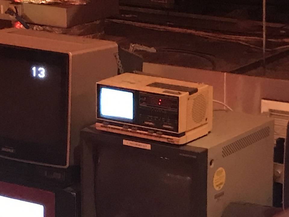
I got immensely lucky. The exact model turned up on eBay almost immediately after and at that point I knew this was meant to be.
The path of least effort seemed clear – hook this up to a Raspberry Pi and configure it to display some personalised dashboard. I chose a Raspberry Pi Zero for its low power draw and cost.
Alas, it turned out to be a bit harder than expected. TVs of this generation consume modulated analog signals (often called RF, for “radio frequency”) either from an attached antenna or external source, and my Saisho is no different. But Raspberry Pis do not output RF – only HDMI or composite video. (The difference between RF and composite is a bit like the difference between AM and FM radio – both use analog signals but apply different modulation techniques.) So I was also going to need a modulator to convert the composite output into RF modulated signal.
I was successful – but not without a lot of learning along the way. This post is a testament to the learning. Come along with me if you want to make your own.
Step 1: attach something to the Raspberry Pi composite output
As mentioned, the Raspberry Pi Zero has a composite video output but it’s not connected to anything on shipped boards because most people don’t need it. The two pins marked “TV” produce a composite video signal.
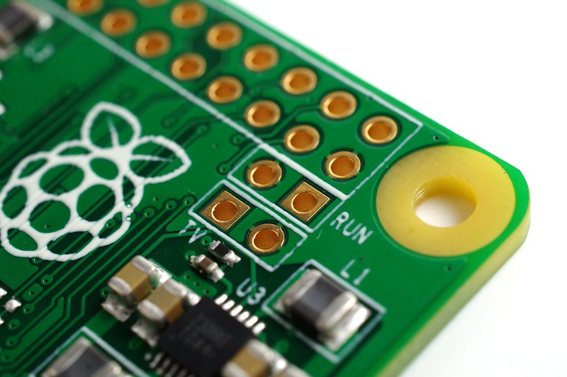
You could solder wires to those pins directly but a better choice is soldering some socket headers – that makes it easier to disassemble if you want to repurpose the Pi. So firstly I soldered some sockets to the pins.
Then I took a phono lead and cut it up, and soldered the two exposed wires to two plug headers, making sure to insulate the two ends from each other with some heat shrink.
Great, now we can plug a phono lead into our Raspberry Pi composite output. If you have a source that can accept composite video (like a pre-2015 but post-1990 TV) you can plug it in to the yellow socket and verify your work.
For how to set up a Pi, I will leave you in the care of the instructions on the Raspberry Pi website.
Step 2: acquire a modulator and wire it up
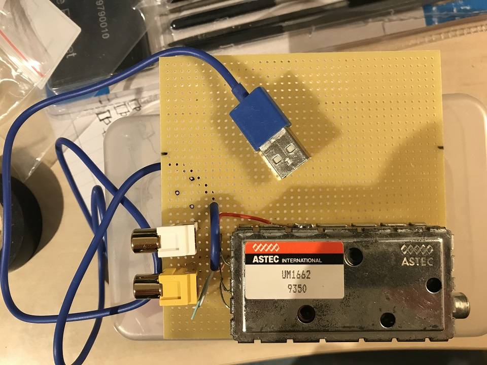
No-one is really making modulators anymore that are any good – the modern ones are all designed for the US market and hence all modulate to channel 3 or 4 which is out of range of the demodulator in the Saisho. I got this ASTEC UM1662 modulator because it modulates to channel 36.
The datasheet sets out how to wire it up quite simply: the case needs to be grounded, the middle pin on the modulator needs to be at 5v and the pin nearest the edge is for the video signal.
For future proofing I decided to attach the modulator to a separate board with its own sockets, so it could potentially be detached and used for something else easily. So I soldered two phono sockets for the video and audio inputs. I also added a USB cable to provide 5v power. I should perhaps have also added a proper power regulator as the quality of USB power outputs is pretty variable – initially I wanted to run it using the modulator of the Raspberry Pi’s USB port but this introduced a lot of noise into the picture.
The modulator comes with little hooks on the underside – I made some holes for these in the board and it sits in quite snugly. For convenience I also mounted the Pi onto the modulator board with some PCB feet, which took a frustrating amount of drilling.
I was now able to connect the Raspberry Pi to the Saisho with a standard RF cable. The results were disappointing: clear evidence of some signal but flickering and failure to lock to a picture. Some ancient knowledge suggested this was an incorrect frequency problem, and I was right – thankfully this is not a noise issue but a Raspberry Pi configuration task.
Step 3: set up Raspberry Pi and services, including remote control and PAL
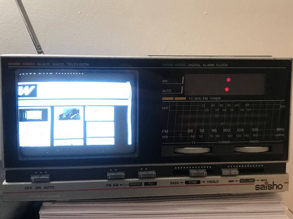
One key understanding is that by going back to composite we are now once again at the whims of NTSC and PAL. By default the Raspberry Pi outputs composite video at 60Hz (NTSC) whereas for the Saisho it expects things to be at 50Hz (PAL). So we need to change the Raspberry Pi standard definition video mode to PAL. Note also that the composite video is always output at a set resolution – it can’t be customised. Once set correctly, I was rewarded for my epiphany with a still (if not exactly crisp) terminal – this was a joyous moment. The remaining steps were a small matter of configuration.
To display something from the internet I ran an X server and booted Chromium – this is a pretty lazy and heavyweight solution, but it’s pretty much the only way to display something from YouTube these days, and by this point I’d been convinced that instead of a yawn-a-minute personalised dashboard I actually wanted to see live penguins. A boot into X and then Chromium showing a YouTube embed achieves that.
In order to make this survive power resets, I wrote a service file. I also enabled some simple remote control and morning auto-start. To see the configuration you can check out this repository on GitHub.
With those final flourishes the prototype is complete – video output onto the Saisho screen from a Raspberry Pi.
What’s next
The project is not over though. Firstly there is no audio – in composite world that comes via a separate channel which I haven’t hooked up. This setup also takes three whole mains plugs (one each for the Saisho, Pi and modulator, which seems to minimise noise). There is therefore more work to be done.
I’d quite like to remove the need for an external modulator. This would make it possible to buy just the old device and the Raspberry Pi and not be reliant on dwindling modulator stocks and soldering faff. It should be possible using just GPIO pins and software to output a modulated signal, but I’m not really aware of how hard that’ll be yet – I’ve seen some software defined radio work on the Pi that seems promising.
A future/alternative stage would be to internalise the Pi to the Saisho and take over all of the case buttons and internals. This will also remove the need for a modulator because we could (presumably?) hook a signal up to the electron gun directly and skip the modulation/demodulation phase. It would also allow automatic control of the clock and software-defined powering on and off of the TV. Given that this would be a permanent change to the Saisho, I’d want to make sure I know what I’m doing before attempting it.
Final BOM
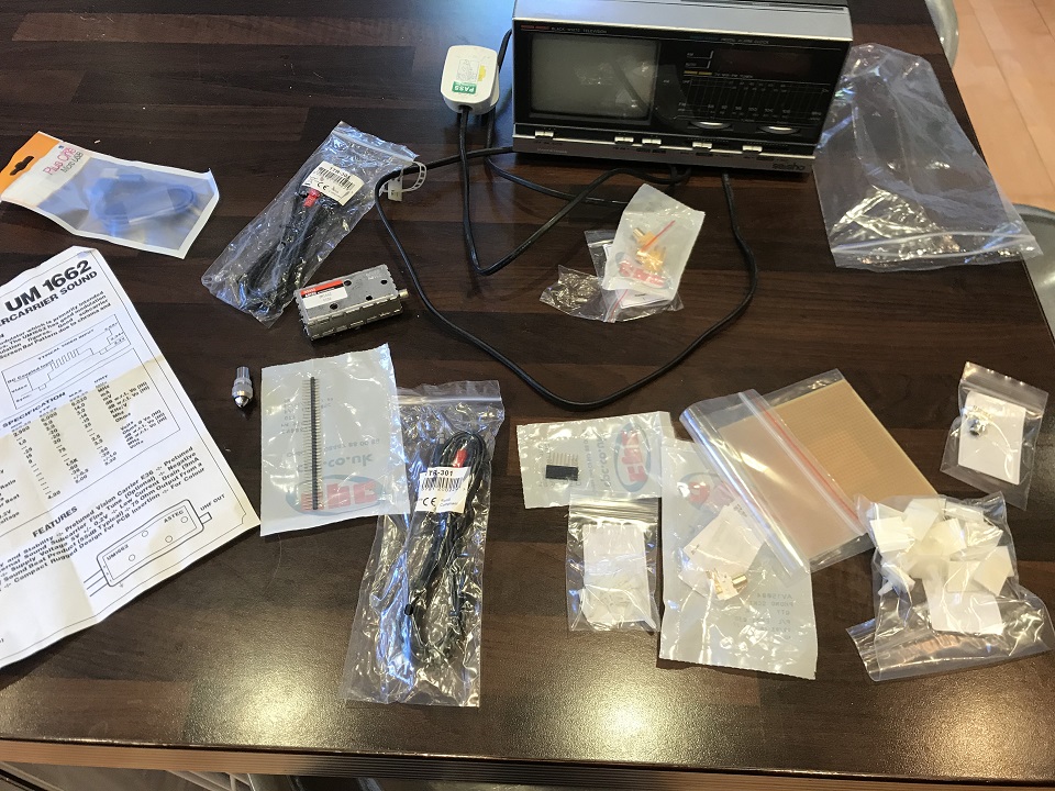
As well as the Raspberry Pi, Saisho and modulator, you will also need:
| Part | Quantity | Purpose |
|---|---|---|
| USB cable | 1 | Snip one of the ends off and use it to powering the modulator |
| Headers – socket | 2 | Exposing the composite TV out |
| Headers – plug | 2 | Attached to the end of the phono cable and plugged into the TV out sockets |
| Phono socket | 2 | For modulator board, one each for audio and video |
| Phono lead | 1 | Cheapest way to get some phono plugs attached to a wire – snip this in half |
| Coaxial cable | 1 | To go between the modulator and the Saisho |
| Matrix board | 1 | To hold and wire up the modulator |
| PCB supports | 4 | Attach the Pi to the modulator board – much drilling involved |
I also used a soldering iron, solder, small lengths of wire, and some heat shrink.